It looks like I've linked you here myself. Linking people to a blogpost I wrote is often a bit akward, especially at work.
I likely shared this blog in an attempt to further a conversation. Usually the post does a better job at succinctly sharing information than I could by talking.
In any case, I hope me sharing this post doesn't come across as humblebragging, that's really the opposite of what I'm trying to achieve.
Thanks for reading!
Window Opener Project30 min read
Opening a window using a custom PCB, 3D printing and home-automation
The Problem
Every year from roughly early April to late May, when we start sleeping with an open bedroom window, I experience the same first-world problem. At the crack of dawn of each new day, I get woken up by chirping birds as they let us know the sun is about to come up. While the early morning chirping subsides as summer replaces spring, for those 2 months, I have to deal with this mildly infuriating circumstance by getting out of bed, closing the bedroom window and then trying to fall asleep again knowing the morning is near.
So naturally, one morning at 5AM I decided to do what any self-proclaimed home-automation aficionado would do: automate the opening and closing of the window. The start of a 2 year journey…
The Plan
While I had build some simple electronics circuits before, I’ve always identified as a software-more-than-hardware type of person. At a high-level, the plan was pretty straightforward though:
- Build some motorized widget connected to a micro-controller board (probably the wifi-enabled Wemos D1 arduino-clone which I had used before)
- Add some buttons that let you open/close the window manually when desired
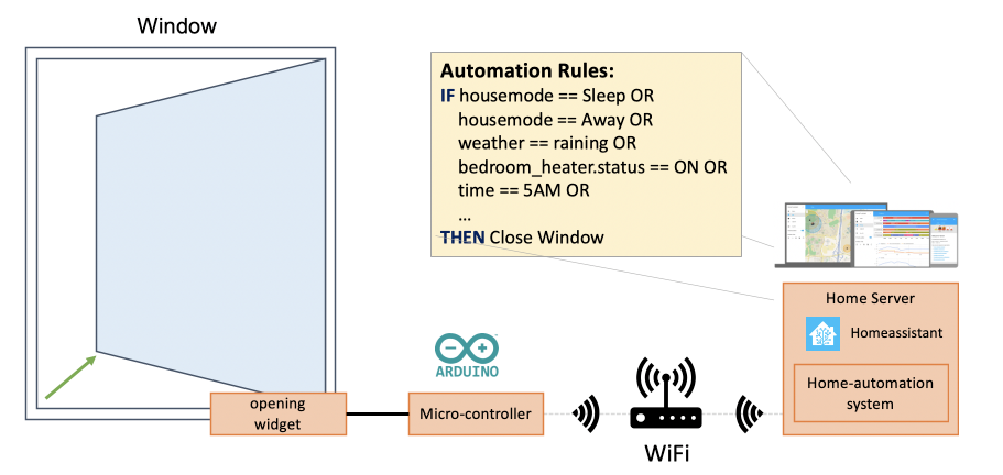
- Program the micro-controller to “talk” to my existing home-automation system
- Configure my home-automation setup to intelligently open and close the window
Steps 2-3-4 I wasn’t too worried about, since I had basically done all of those things before - easy-peasy ✅. However, coming up with the motorized widget to open the window, that was going to be the challenge. Especially since I didn’t really have experience with electric motors outside of some beginner arduino tutorials.
Coming up with the high-level plan was the easy part!
Servos
After some initial research, I found this Arduino Controlled Window for Cat project, which uses a servo motor with a swivelling arm attached to open and close the window.
So I tried building the same thing. What I thought would take me 2-3 hrs at most, ended up taking much more time across multiple different afternoons (months apart). While some of the required parts took time to research, order and arrive (a powerful servo, servo mounting bracket, small bolts, hinge, etc), it was the swivelling servo arm that was causing most problems.
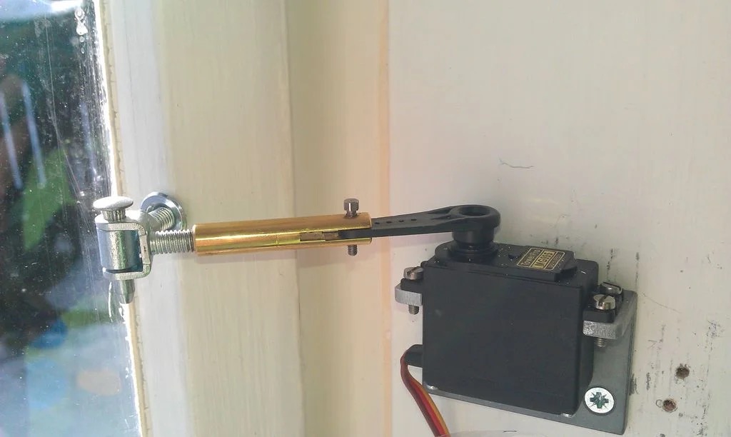
The servo motor widget as shown in the Arduino Controlled Window for Cat project (their photo).
You see, the length of the swivelling servo arm has to be very exact for this setup to work. If the arm is just a tiny bit off, the whole thing becomes a janky mess that tears itself apart. This is what the threaded pipe and bolts in the picture allow you to do: fine-tune the length of the arm after installing the motor and hinge.
Because I didn’t have the exact pair of matching pipe and bolts and thinking I could “just make my own modified version”, this turned out to be a big challenge. After trying and failing to precisely measure and cut a servo arm of the exact length multiple times, I eventually became frustrated and decided to try a different approach all-together.
Two things I learned from this:
- How challenging it can be to find seemingly simple parts, especially when you don’t know the right terminology
- How little I understand about (electro)mechanics. Swivelling arms, turning motors, cogs, sprockets, bearings, hinges and how they all work together 🤯. Even the movement dynamics of this simple contraption threw me off a few times.
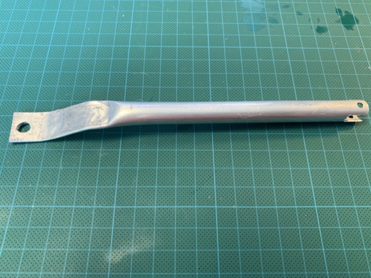
My custom servo arm. This didn’t work - at all.
Starting over
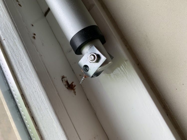
After another break from this project I decided to take a completely different approach and more closely mimick the telescope window stay that was already in place for the window.
The idea was that instead of using a servo motor, I’d use a linear actuator together with a simple control circuit using relays. Not without a bit of surprise, I got the linear actuator+relay setup working fairly quickly.
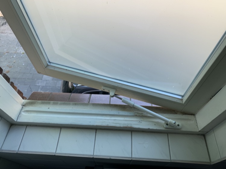
Telescope window stay. Yes that window frame needs some cleaning :-)
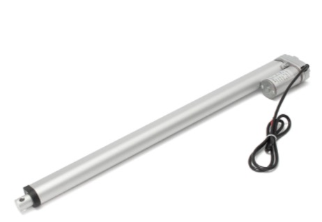
Linear actuator. The arm extends when supplying +12V and retracts when supplying -12V.
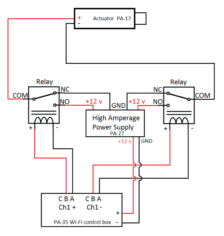
A schematic I found online outlining how support both extending/retracting the actuator arm using 2 relays and a dedicated 12V power supply.
Yet, as with the servo motor, figuring out how to attach the actuator to my window frame turned out to be the bigger challenge. After trying out a myriad of different constructions and hinges on a few different afternoons, I came across Steel Hanger Strap which finally allowed me to work out a construction that sort of worked.
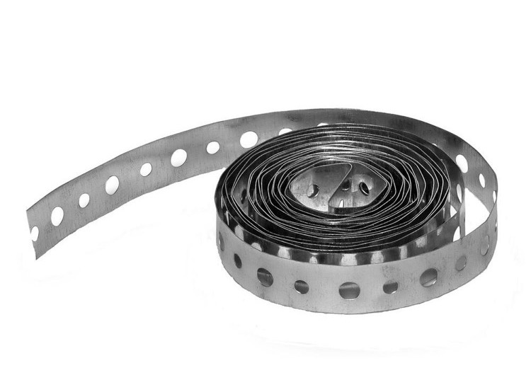
Galvanized Steel Hanger Strap. You’ve probably seen this before, just a metal strap with holes in it.
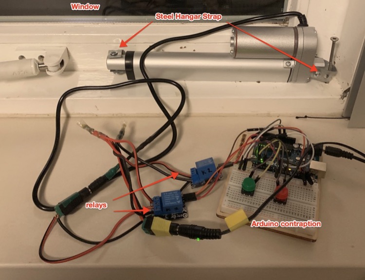
Initial working prototype
.](prototype-fritzing.png)
Wiring diagram of the setup. Created in Fritzing.
.](prototype-kicad.png)
Circuit schematic - created in KiCad.
This felt like a big milestone. I decided to build an identical copy of the whole thing to start iterating on the design while keeping one in place and actually using it.
By why you ask? Behold! pic.twitter.com/6suamNmzJB
— Joris Roovers (@jorisroovers) March 1, 2020
Incremental improvements
Everyone who’s ever build something “production grade” (i.e. ready to be used in the real-world by non-experts) knows there’s a massive difference between a working prototype and a finalized product.
For this project as well, there were a bunch of improvements I wanted to make before putting this in full-time use. In addition, there was a huge opportunity for me to learn here - most of the improvements I had in mind involved a lot of research and tinkering.
The improvements:
- Single wall-adapter: The circuit requires 12V to actuate the motor and 5V to power the circuitry. In the prototype I accomplished this by using 2 separate wall adapters, but I really wanted to use just one.
- Modular: The prototype consisted of a single rig. I wanted to be able to easily decouple the motor and power supply form the brainbox without the need for tools (e.g soldering iron).
- Micro-controller software: While this was the part I was more experienced with, I still had to write the (non-prototype) code. There was also some new technology I wanted to look into.
- Manual controls and override: Ensure that in addition to opening and closing based on automation rules (time of day, weather, etc), we should also be able to open and closed the window using buttons. The button controls should take precedence over automated action for safety reasons.
- Compact and rigid design: The prototype circuit was large and fragile. I wanted to have something much more compact and solid that could be wall-mounted in a small enclosure.
All of these were worked on in parallel as changes in one area heavily affected other areas. The remainder of this post describes the details of these improvements.
Single-wall adapter
The goal here was to be able to use a single 12V wall adapter and split out the power out in one 12V (for the motor) and one 5V line (for the control circuit).
The first thing I tried was using a LM2596S DC-DC buck converter. The benefit of using a circuit board like this one, is that you can really treat it as a black-box. You feed current into it and get a configurable current as output - how this conversion happens is opaque to you.
This actually worked great. However, because I wanted to save on space and integrate this in a PCB (see further), I started investigating using a 7805CV linear voltage regulator. This voltage regulator is much smaller than the buck converter, but has the disadvantage that you have to build some of the supporting circuitry yourself (most importantly adding some capacitors for noise suppression). You also have to take care of heat dissipation by adding a small heatsink.
After some research and experimentation I got this working and this is what I ended up going with. I did later learn that buck converters are generally much more efficient than linear voltage regulators, so that will probably influence my choice in the future.
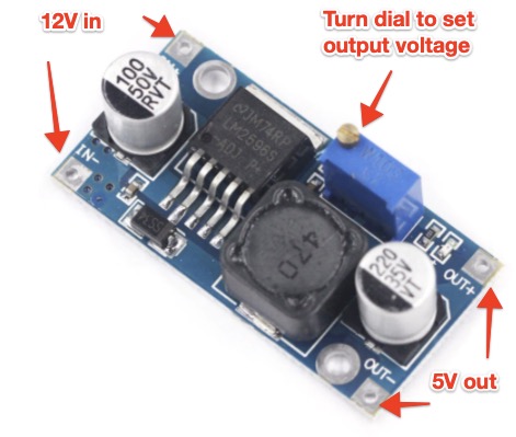
LM2596S Buck converter
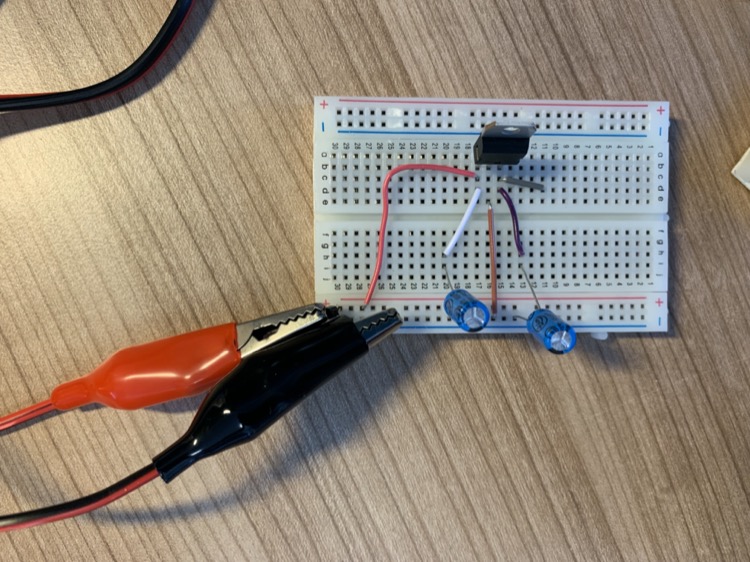
7805CV linear voltage regulator testing.
Modularity
In the original prototype, the linear actuator had a fixed connection the control circuitry which in turn had a more-or-less fixed connection to the power supply.
I improved this using power jacks for both the power-supply as well as the motor connection. This made the whole thing easier to move and install. It also allowed for more rapid prototyping as I now could easily upgrade the control circuitry while keeping the motor and power supply in place.
In practice, it meant I always had two versions of the control circuitry: one that I was working on and one that was installed and doing its actual job. This worked out great.
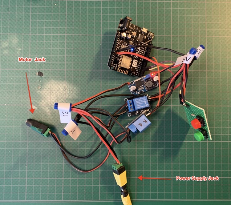
Using power-jacks to connect the motor, control circuitry and power supply.
Micro-controller software
Like mentioned at the start of this post, I had chosen the arduino-compatible Wemos D1 as the micro-controller for this project, because 1) it’s cheap and 2) prior experience.
At first I thought I’d write all the code in C using the Arduino IDE toolchain as this is what I had done before. Interested to learn something new though, I explored micro-python as an easier way to achieve what I wanted. This worked out very well, I personally find it a less opaque way of working than using the classic Arduino toolchain.
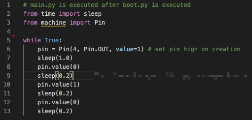
Blinking an LED using MicroPython - piece-of-cake 🍰.
However, since I eventually wanted to integrate this with home-assistant, I also looked into ESPHome - which had been on my TODO list for a while.
In a nutshell, ESPHome allows you to easily integrate ESP32 and ESP8266 microcontrollers with home-assistant by creating a YAML file that specifies some general info (wifi credentials, devicename, etc) and a set of input/output pins. After setting up the corresponding component in home-assistant (takes 30 secs), those inputs and outputs pins become available as sensors.
As with other sensors, you can then use home-assistant’s automation rules to remotely control that micro-controller and integrate it with the rest of your stack.
I had this whole thing working and doing what I wanted within 2 hours or so - highly recommended.
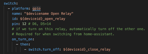
ESPHome config of a pin hooked up to one of the relays. Note that you can also add some on-device automation rules (on_turn_on) - these are useful to implement fast and fully local logic. Here I used it to ensure the 2 relays (open and close) are never switched on together.
on_turn_on) - these are useful to implement fast and fully local logic. Here I used it to ensure the 2 relays (open and close) are never switched on together.Manual controls and override
While it’s really handy to be able to control the window via home automation, I wanted to also be able to control the window “manually”, so that I didn’t have to pull out my phone to control the window on-demand. In addition, I wanted to make sure we could easily override any potential finicky automated behavior.
So I added 2 buttons to do exactly that. The related circuitry and code was comparatively straight-forward.
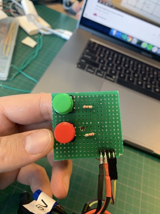
Second prototype. Green to Open, Red to Close. Common sense, right?
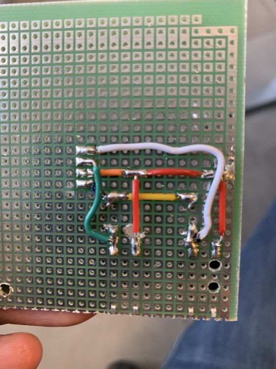
Prototype Backside. Nothing professional, but I was still pretty proud of this soldering job.
The result of connectivity loss between the control circuitry and my home-automation stack while the window was being opened 😬
Compact and rigid design
This workstream undoubtedly had the most iterations.
I started out by improving the wiring by using thicker gauge and wire-nuts. I also soldered some wires to the micro-controller, selected an electric junction box as enclosure and carved some holes in the junction box for power and buttons (using a rotary tool, i.e. a dremel).
While that looked ok, the whole thing was still too bulky to comfortably fit in the enclosure. On top of that, the whole circuit became finicky because what I believe to be short-circuits of wire-ends touching each-other unintentionally.
Given the amount of time I had spent, this was frustrating and I decided take a brief pause on the project.
The enclosure I tried first. While I could make everything fit, it really was way too packed in the box.

Frustrated tweet, needed a break after this.
When picking this back up a week or so later, I decided to try out building a custom PCB instead. While there’s a bunch of tools out there that allow you to design PCBs, I eventually settled on using EasyEDA for its simplicity. While I had never designed a PCB before, I quickly discovered that the basics are not that hard. As I told a friend: “If you know how to build Powerpoint slides, you can figure out how to design a PCB using EasyEDA as well”.
 (recommended!). They threw in the electrical tape for free!](jlcpcb-test.jpeg)
A test PCB I had put together and ordered via JLCPCB (recommended!). They threw in the electrical tape for free!
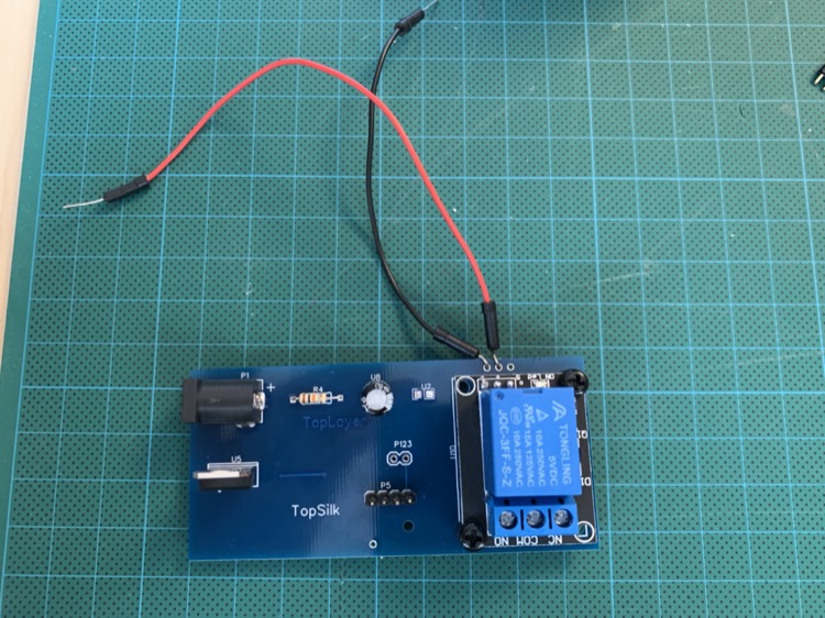
Same PCB but with some components soldered on. This PCB doesn’t do anything, I was just trying out different component placements, options and layouts.
After some initial testing, I set out to build to real thing and had it manufactured in China. I was really surprised how cheap and fast this was. ~2 USD for manufacturing (yes, 2 dollars!), ~20 USD for expedited shipping, arrived within 5 days. Amazing.
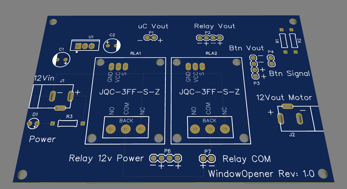
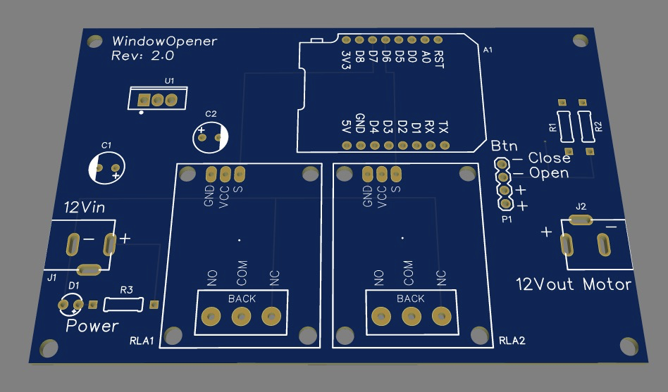
The PCB I came up with. Maybe not exactly professional once you have a closer look, but still proud of it!
All soldered up
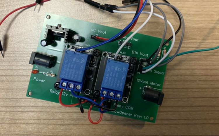
Second revision.
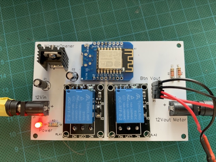
The 2nd revision incorporated the micro-controller directly on the board and got rid of any remaining wires except for the external button controls. Also, white-colored PCBs look pretty cool 😎
Enter 3D Printer
3D Printing was something I always thought was cool but for some reason I believed that entry-level 3D printers required a lot of setup and constant calibration while producing mediocre results. Turns out…I was completely misinformed and had a very outdated perception. After a good friend of mine bought an AnyCubic i3Mega printer and started sharing some of his prints - I decided to take the plunge and get the same model.
After spending a day or two tinkering and learning the basics of Fusion360 (which by-the-way, is free for hobbyists), I started working on a custom enclosure as well as updated hinge mechanisms to replace the hanger-strap makeshift hinges I had created before.
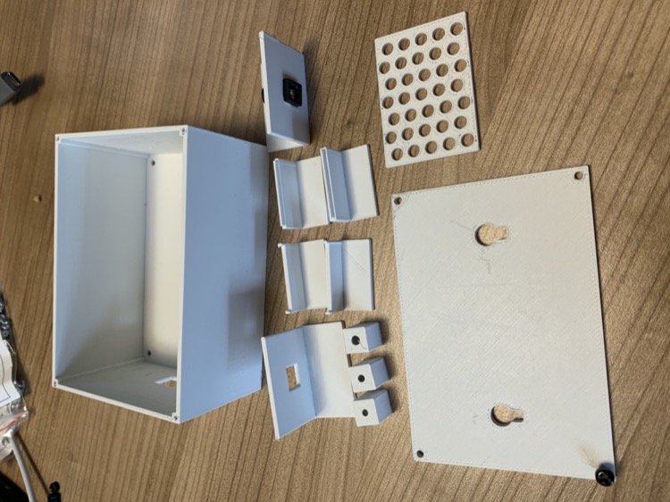
Various test prints and experiments for the enclosure.
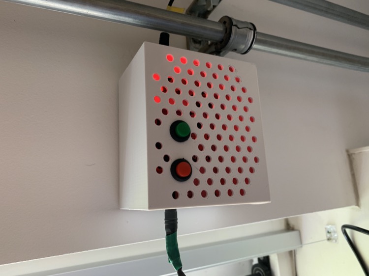
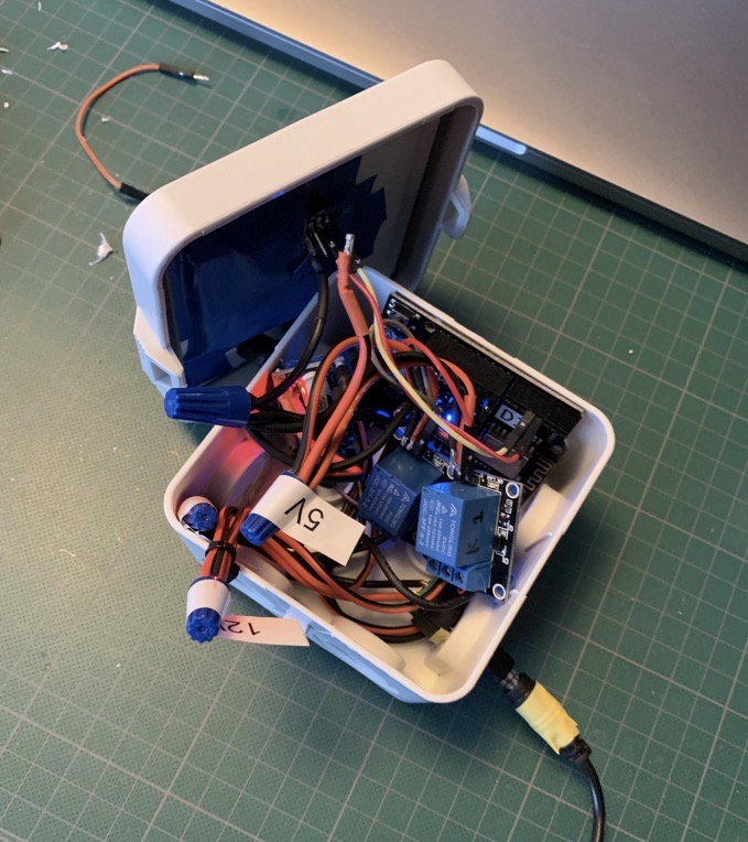
Final enclosure mounted next to the window. The front is perforated to provide passive air flow for circuitry. The red glow is from an LED I placed on the PCB.
Not only did this printer significantly improve the outcome of this project, it added a super-power to my toolbox and it is so much fun. If you’re a tinkerer and don’t have one yet, I can highly recommend it.
One of the hinge mechanisms in Fusion360
Closing Thoughts
Here’s a video of the final result - you might notice a few more tweaks I haven’t described in detail in this post. You should be able to unravel those from the reference and source material linked at the bottom. You can also tweet me @jorisroovers if you have any questions!
Before this project, I had only a vague understanding of electrical components, motors, PCBs and 3D Printing. While I’m still only a beginner in all these fields, I learned a ton and had a lot of fun along the way. For me it really helps to have a concrete purpose in mind when I start on a project, preferably to build something I will be using every day, and then learn what’s needed along the way. This personal use-case is what keeps me from abandoning the project when there’s setbacks (there were a lot of those in this project!), as well as make any new skills stick.
While there’s still room to improve on this project (more compact PCB, enclosure, etc), I’m happy with how it currently functions and am starting to hit diminishing returns on what I’m learning. Time to go work on the next project!
I've uploaded all relevant schematics, diagrams, CAD models, PCB designs and source-code to Github.